Back when I was a Computer Science student at university (RIT) I took the course Computer Graphics II. One of the assignments for the class was to develop our own ray tracer from scratch. It was both a fun and challenging project.
For the assignment we had to track our progress online. I did so via my personal website over to course of 9 blog posts. I have long since deleted that website because at the time I wasn’t serious about blogging.
But the ray tracer project stuck with me. As a result, I have decided to reupload the original posts with a little editing for clarity. Enjoy!
Note: I do not show code in this post. This was a university assignment, so the sharing of code was not permitted for academic reasons.
The posts showcase various checkpoints along the way. If popular, I may make a post on how to make a ray tracer (with pseudocode) in the future.
| Link | Checkpoint | Original Date |
|---|---|---|
| Part I | Reproduce ray tracing scene with existing 3D software | 21 Mar 2012 |
| Part II | Create a 2D ray tracing viewport along with geometries | 29 Mar 2012 |
| Part III | Add Phong shading to ray tracer | 11 Apr 2012 |
| Part IV | Add procedural shading to ray tracer | 11 Apr 2012 |
| Part V | Add reflectance to a sphere | 26 Apr 2012 |
| Part VI | Add transparency to a sphere | 1 May 2012 |
| Part VII | Add Ward and Reinhard tone reproduction | 6 May 2012 |
| Extras | Showcase extras for bonus points | 6 May 2012 |
| RenderMan | Experiment with RenderMan | 1 May 2012 |
Part I – Setting the scene
Ray tracing is an illumination technique within computer graphics, whereby “rays” are traversed (backwards) from a viewer to a light source in order to render a realistic image. This is a reversal of real life, where light travels from a light source to a viewer. Ray tracing allows for complex scenes to be rendered because during backwards traversal the shading, reflectance, and transmission of one or more surfaces along the way are all calculated.
Ray tracing was first described in an article titled An Improved Illumination Model for Shaded Display (1980) authored by Turner Whitted. There he describes the steps he took to build a ray tracer. The article, despite advancements over time, is still a worthy read.

To start off the assignment, we were supposed to “set the scene” based on the original ray tracing image. I use Blender (v2.62) to do this.

In order to imitate Whitted’s image I need to view the scene from the appropriate angle. I use trial and error to place my camera (also known as viewer or eye) at x, y, z coordinates that match the camera in Whitted’s image.

I use the following dimensions:
Object A (close): x = 1.081, y = -0.240, z = 3.250
Object B (far): x = -3.000, y = -3.000, z =1.000
Camera: x = 11.141, y = 0.469, z = 6.518
Light: x = 9.390, y = 0.275, z = 8.631
Because the objects are spheres, rotation is irrelevant to the lighting of objects. However, I cheated with Object A by scaling it to 1.5x the size of Object B to create a sense of depth. I also added a floor to the scene, and eventually rotated the camera to x = 72°, y = 0°, z = 98° so that the scene looks more like the original image.

Part II – Camera modeling
After experimenting in Blender, it is time to start programming. I decide to use Java for programming the ray tracer.
First, I have to place a camera in space and create a viewport. Next I populate the scene with shapes and implement basic ray tracer functionality (i.e. shooting rays at objects, we don’t have to worry about a light source for now).
Somewhere along the way I stared running into funky bugs. The good news is: at least the program compiles and runs.

After several hours of debugging, I make significant progress. I found out what was wrong, my viewport (i.e. canvas) coordinates are were used for calculating my ray’s vectors. This is wrong because viewport coordinates are used for spawning rays and drawing a 2D result, but not for vector calculation. As a result all but 1 ray missed the spheres (only the center ray hit because it had no angle). To solve this I had to define a pixel width and height relative to camera coordinates. In the render below I fixed this. You now see 3 colors: yellow is the plane, red is the sphere, and blue is the sky.

Finally, after several more hours I achieved the required results. My previous render used flawed math (duh!). I also added a plane, which involved some nasty vector math, and changed the colors (the red was becoming too much).

Part III – Basic shading
In 1973, Bui Tuong Phong wrote his dissertation on a reflection model that would come to bear his name. These days, Phong shading has become an integral shading technique within in computer graphics. The shading technique is recognizable by its plastic look.
For this checkpoint, we need to implement Phong shading in our ray tracer. This has been quite a difficult submission for me, and I struggled a lot with the vector calculations. Even though it is not perfect, here is my implementation of Phong shading. There are still some changes I would like to make, mainly, the shadows don’t appear perfectly.

Part IV – Procedural shading
For checkpoint 4, we need to implement procedural shading. Procedural shading uses mathematical formulas to determine the color or texture of a surface. In my first iteration, I implemented the procedural pattern with Phong shading turned off.

In my second iteration, I add Phong shading functionality to the procedural pattern. In the first image below, the spheres and the procedurally generated floor use Phong shading. In the second image, shading is turned off for the floor (this also causes the spheres' shadows to disappear):


Part V – Reflection
For the next step, we needed to add reflectance to one of the spheres. This was not too difficult, because my illuminate method was nicely set up for recursion. Also I managed to fix the noise in the Phong shading shadows, and applied antialiasing to smoothen the edges.
I still had some issues in my scene, the light was a little too bright and the reflection had noise. Eventually, I managed to fix the issue of noise with epsilon correction (a precision threshold for floating point calculations). Below are two more images, one with 2 lights, and one with a single light. The shadows could still use some improvement, they are very dark under single light conditions.


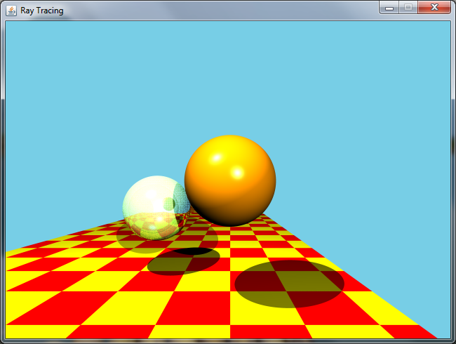
Part VI – Transmission
In this submission of the weekly assignments we are supposed to create a transparent sphere. On the side I also experimented with adding custom textures, for which I used a wallpaper image found online. For transmission, the first result I got was a bit grainy and dark, and lacked total internal reflection (TIL).

In my second attempt, I made the sphere lighter and added TIL. Despite adding epsilon, it is still grainy.

After a couple hours of trail and error coding, I was finally able to remove the grainy dots in my sphere. The main issue was imprecise intersection detection within the sphere. This resulted in the greater of 2 intersection distances (distance to sphere’s back instead of front) to occassionaly be used.
With this checkpoint, I have managed to recreate Whitted’s original ray tracing scene, and also created a scene with the wallpaper texture added:


Part VII – Tone reproduction
In this checkpoint of the ray tracer, we replicated tone mapping (also known as tone reproduction) using the Ward and Reinhard methods. Tone reproduction is a technique used to manage the large differences in dynamic range that can occur between a real world scene and a printed or digital image of said scene. One application of tone reproduction is the manipulation of an images in an attempt to perceptually reproduce their equivalent real world scenes.
The first method is was authored by Greg Ward and published in Graphics Gems IV: A Contrast-Based Scalefactor for Luminance Display (1994). The second method was authored by Erik Reinhard et al. (2002) in Photographic Tone Reproduction for Digital Images. Here are my results at different illuminations:


Reinhard tone reproduction does not seem to be well suited with this particular implementation of ray tracer. The difference between 1, 1000, and 10000 nits appears to be minimal, all yield a dark scene.
Extras
For our ray tracer is was possible to obtain bonus points with extras. Here are images of the 5 extras I have implemented, you might have seen some of these in previous checkpoints. I used or added:
- Super-sampling
- An extra shape
- A second light source
- A second procedural pattern
- A texture


This concludes the multi-checkpoint ray tracing assignment!
RenderMan
NOTE: For Computer Graphics II, we also had to experiment with RenderMan. RenderMan is Pixar’s in-house animation software. We were using an older version, but this software is quite powerful and used in making the animated movies you known and love. While unrelated to the ray tracing asssignments above, I included it in this post for the sake of completion.
We are to generate 3 scenes: the first by tweaking a given file, the second by adding some third party shaders, and lastly enter a submission to the best RenderMan render competition. Here are my submissions:

For the second submission I used some stock shaders like TLFresnelPlastic, LGVeinedMarble, and LGRustyMetal. Even though it was not overly complex it helped me understand the basic. Also, one more thing, don’t forget to compile the shaders before you run prman!

For my RenderMan competition submission, I found some toon shading shaders. Since my interest in toon shading is profound I decided to give it a try, I ended up making some psychedelic teapots:

NOTE: After my classmates voted, my submission into the RenderMan competition ended up winning 3rd place. I won a $20 book gift card!